Short answer: Mini split outdoor unit clearance is model- and layout-specific. Use the exact outdoor unit's installation diagram, including its intake, discharge, service side, overhead space and wall arrangement. A single distance quoted for a brand is not enough. Multiple walls, stacked units, snow and screens can change the requirements. Have the installer approve the actual site before placing equipment.
Why one clearance number is misleading
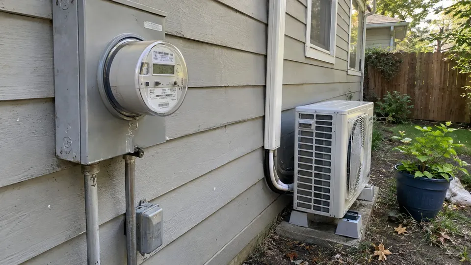
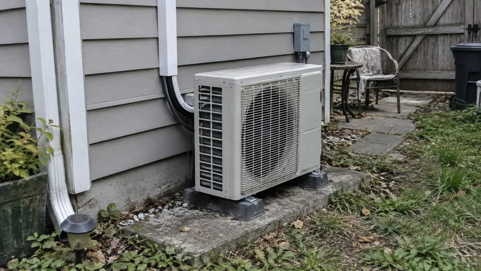
An outdoor unit needs space for airflow and service. Its intake and outlet are not the same face, and a nearby fence can act as a wall. A requirement for a unit facing one wall may not apply inside a three-sided enclosure.
Do not use this comparison as permission to move or install a unit. It is a homeowner planning guide for reading the right diagram and discussing the site with an installer. Refrigerant, electrical, anchoring and relocation work need qualified personnel.
Step 1: Match the full model and wall pattern
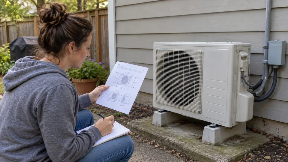
- Record the complete outdoor model, including its suffix.
- Find its current installation manual and any applicable technical bulletin.
- Identify the air inlet, fan discharge, service side and overhead space in the diagram.
- Count the walls or solid obstructions around the planned location, including fences and privacy panels.
- Have the installer select the diagram that actually matches that arrangement.
Do not assume a replacement unit can reuse the old equipment's clearance. A higher-capacity model or different cabinet can have another requirement.
Three manufacturer examples, not brand-wide rules
These values come from the specified documents and their pictured arrangements. They are deliberately not a generic BTU chart.
| Exact source/example | Published space | Conditions that must remain attached |
|---|---|---|
| Mitsubishi MSZ-HM12NA-(U1)(U2) / MUZ-HM12NAH-U1 submittal | Required-space drawing shows 4 in (100 mm) or more at the rear and illustrated side gaps, 8 in (200 mm) or more at the front, and 14 in (350 mm) or more on the service side | Rear note requires front and sides clear; front note requires any two of left, right and rear clear. Read the complete drawing, not this row alone |
| Daikin Oterra manual 3P601788-4K, Class 09/12, one-wall pattern | More than 50 mm at the inlet-side wall; more than 100 mm at an outlet-facing wall | Diagram treats these wall cases separately; exhaust-side wall height is 1200 mm or less. Other wall patterns and model families differ |
| Gree archived Multi Revision A manual, MULTI18/24/30/36/42HP230V1AO | Drawing A overhead: 20 in (500 mm); B service side: 24 in (610 mm); C discharge: 78 in (2000 mm); D opposite side: 12 in (305 mm); E rear inlet: 20 in (500 mm) | This is that listed Multi family and its A to E diagramm, not every current Gree unit |
The source drawings include geometry that a table cannot fully carry. For example, Daikin's Class 18/24 one-wall pattern gives different distances from Class 09/12. Its two- and three-wall diagrams also change the gaps. Do not choose the smallest number anywhere in the manual and apply it to all sides.
Mitsubishi's HM12 submittal is an illustrative planning source, not a replacement for the exact installed unit's installation instructions. Confirm the current revision with the installer if model labels, suffixes or documents differ.
Step 2: Check the actual space without altering equipment
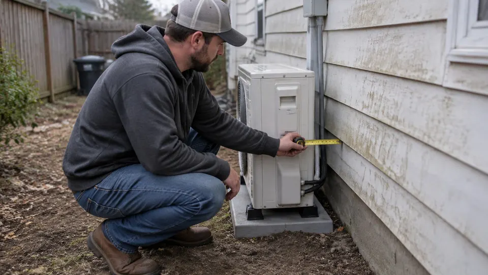
Measure from the reference faces shown in the correct diagram, not from a convenient nearby bracket. Record the gaps and photograph the surroundings. Keep clear of the fan and hot or energized parts; do not remove covers to measure.
Include anything that can become an obstruction: hedge growth, stored bins, a gate that opens in front of the fan, snow buildup and a cover or canopy. Keep the service side accessible for inspection and repair, not just enough space to make the unit fit today.
If there are stacked units, a narrow alley, tall walls or an enclosure, ask for the manufacturer's layout-specific instructions. Do not add individual minimum gaps together and assume the resulting box will work.
Snow, drainage and screens need another check
In snow climates, ground clearance and snow protection are separate from a wall gap. The unit must not be buried or have its intake/discharge blocked. Ask the installer about local snow depth, drifting, defrost drainage and any manufacturer-approved stand or protection. See the cold-weather guide for operating checks, not installation dimensions.
A privacy screen can block flow even if it is slatted. A canopy can also alter the overhead arrangement. Obtain approval for its design and position before building one. Do not wrap or box in an operating outdoor unit.
Daikin's cited manual specifically cautions about drain fittings in cold areas because water can freeze. Do not copy another climate's drain arrangement or drill new drainage holes yourself.
If an existing unit seems too close
Send the installer the model label, surrounding photographs and measured gaps. Ask which diagram applies and whether airflow and service access meet it. Do not move the cabinet, bend piping or extend electrical connections yourself.
If it has weak heating or cooling, clearance is one possible check, not a diagnosis. Use the not-cooling guide for accessible checks and arrange service for persistent trouble. Keep vegetation and stored objects outside the required space, and reassess before adding a fence or deck.
Related reading
- Planning the electrical side too? Read about breaker size.
Sources
- Mitsubishi HM12NA/HM12NAH-U1 submittal, page 2 required-space drawing and conditions.
- Daikin Oterra installation manual 3P601788-4K, outdoor wall-pattern diagrams on PDF page 12.
- Gree Multi Revision A installation manual, listed models and installation dimensions, printed page 8.